
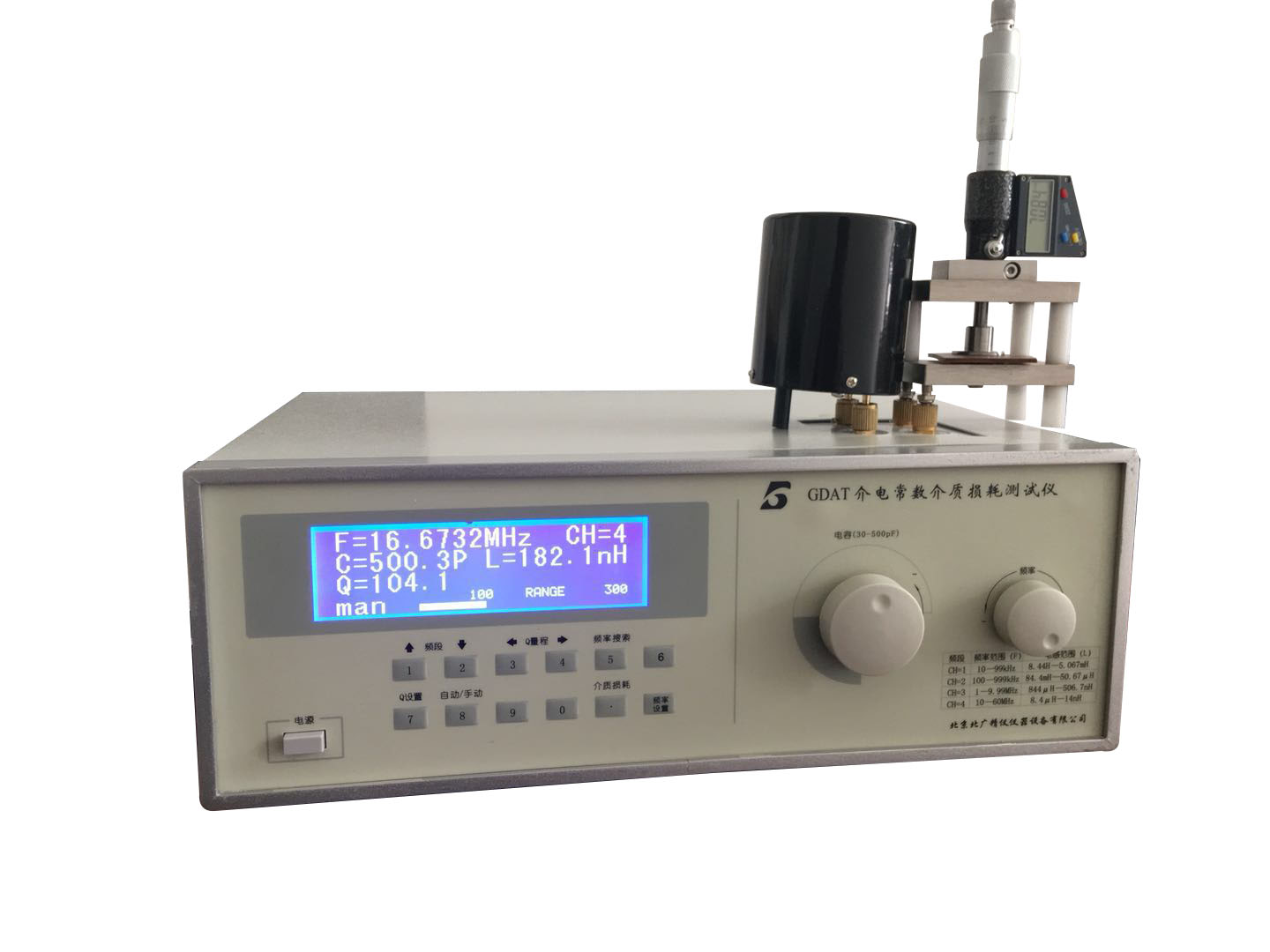
介質損耗因數測試儀 儀器特點:
☆接線簡單(正接法兩根線,反接可使用一根線),所有電纜線均有接地屏蔽,所以都能拖地使用,測量電壓緩升、緩降,全自動測量,結果直讀,無須換算。
☆多種測量方式 可選擇正/反接線、內/外標準電容器和內/外試驗電壓進行測量。正接線可測量高壓介損。
☆ 抗震性能 儀器可承受長途運輸中強烈震動顛簸而不會損壞。
☆ 抗干擾能力強 采用自動跟蹤干擾抵償電路,將矢量運算法與移相法結合,有效地消除強電場干擾對測量的影響,適用于500kV及其以下電站的現場試驗。
☆CVT測量 獨特自激法測量CVT功能,不需外加任何設備,可完成不可拆頭CVT的測量。一次接線(三根電纜,不用倒線),一個測量過程(大約1分鐘),兩個最終測量結果(C1和C2的介損及電容值)。測量過程中文顯示,能實時監測自激電流值和試驗電壓(高壓)值。能消除引線對測試的影響,測量結果準確可靠。
☆VFD顯示 采用新穎的大屏幕VFD點陣顯示器,在嚴冬和盛夏都能清晰顯示。全中文操作菜單,操作提示各種警告信息,直觀明了,不需查閱說明書即可操作。
☆打印 儀器附有微型打印機,以中文方式打印輸出測量結果及狀態。
☆RS232儀器具有RS232接口,與計算機連接便于數據的統計和處理及保存。
☆可選購與計算機通信應用程序。
介質損耗因數測試儀 測試注意事項
a.本儀器應水平安放;
b.如果你需要較精確地測量,請接通電源后,預熱30分鐘;
c.調節主調電容或主調電容數碼開關時,當接近諧振點時請緩調;
d.被測件和測試電路接線柱間的接線應盡量短,足夠粗,并應接觸良好、可靠,以減少因接線的電阻和分布參數所帶來的測量誤差;
e.被測件不要直接擱在面板頂部,離頂部一公分以上,必要時可用低損耗的絕緣材料如聚苯乙烯等做成的襯墊物襯墊;
f.手不得靠近試件,以免人體感應影響造成測量誤差,有屏蔽的試件,屏蔽罩應連接在低電位端的接線柱。
介質損耗:絕緣材料在電場作用下,由于介質電導和介質極化的滯后效應,在其內部引起的能量損耗。也叫介質損失,簡稱介損。在交變電場作用下,電介質內流過的電流相量和電壓相量之間的夾角(功率因數角Φ)的余角δ稱為介質損耗角。
損耗因子也指耗損正切,是交流電被轉化為熱能的介電損耗(耗散的能量)的量度,一般情況下都期望耗損因子低些好。
概念:
電介質在外電場作用下,其內部會有發熱現象,這說明有部分電能已轉化為熱能耗散掉,電介質在電場作用下,在單位時間內因發熱而消耗的能量稱為電介質的損耗功率,或簡稱介質損耗(diclectric loss)。介質損耗是應用于交流電場中電介質的重要品質指標之一。介質損耗不但消耗了電能,而且使元件發熱影響其正常工作。如果介電損耗較大,甚至會引起介質的過熱而絕緣破壞,所以從這種意義上講,介質損耗越小越好。
表征:
電介質在恒定電場作用下,介質損耗的功率為
W=U2/R=(Ed)2S/ρd=σE2Sd
定義單位體積的介質損耗為介質損耗率為
ω=σE2
在交變電場作用下,電位移D與電場強度E均變為復數矢量,此時介電常數也變成復數,其虛部就表示了電介質中能量損耗的大小。
D,E,J之間的相位關系圖
D,E,J之間的相位關系圖
如圖所示,從電路觀點來看,電介質中的電流密度為
J=dD/dt=d(εE)/dt=Jτ iJe
式中Jτ與E同相位。稱為有功電流密度,導致能量損耗;Je,相比較E超前90?,稱為無功電流密度。
定義
tanδ=Jτ/Je=ε〞/εˊ
式中,δ稱為損耗角,tanδ稱為損耗角正切值。
損耗角正切表示為獲得給定的存儲電荷要消耗的能量的大小,是電介質作為絕緣材料使用時的重要評價參數。為了減少介質損耗,希望材料具有較小的介電常數和更小的損耗角正切。損耗因素的倒數Q=(tanδ)-1在高頻絕緣應用條件下稱為電介質的品質因素,希望它的值要高。
儀器技術指標:
☆Q值測量:
a.Q值測量范圍:2~1023。 b.Q值量程分檔:30、100、300、1000、自動換檔或手動換檔。
c.標稱誤差
頻率范圍:20kHz~10MHz; 固有誤差:≤5%?滿度值的2%;工作誤差:≤7%?滿度值的2%;
頻率范圍:10MHz~60MHz; 固有誤差:≤6%?滿度值的2%;工作誤差:≤8%?滿度值的2%。
☆電感測量:
a.測量范圍:14.5nH~8.14H。
b.分 檔:分七個量程。
0.1~1μH, 1~10μH, 10~100μH,
0.1~lmH, 1~10mH, 10~100mH, 100 mH~1H。
☆電容測量:
a.測量范圍:1~460pF(460pF以上的電容測量見使用規則);
b.電容量調節范圍
主調電容器:30~500pF; 準 確 度:150pF以下?1.5pF;150pF以上?1%;
注:大于直接測量范圍的電容測量見使用規則
☆振蕩頻率:
a.振蕩頻率范圍:10kHz~50MHz;
b.頻率分段(虛擬)
10~99.9999kHz
100~999.999kHz
1~9.99999MHz
10~60MHz
c.頻率誤差:3?10-5?1個字。
☆儀器正常工作條件
a.環境溫度:0℃~ 40℃; b.相對濕度:<80%; c.電源:220V?22V,50Hz?2.5Hz。
☆其他
a.消耗功率:約25W; b.凈重:約7kg; c.外型尺寸:(l?b?h)mm:380?132?280。
☆Q合格指示預置功能
預置范圍:5~1000。
☆主要配置:
a.測試主機一臺;
b.電感9只;
c.夾具一 套
低頻電橋
一般為高壓電橋,這不僅是由于靈敏度的緣故,也因為在低頻下正是高電壓技術特別對電介質損耗關注的問題。電容臂和測量臂兩者的阻抗大小在數量級上相差很多,結果,絕大部分電壓都施加在電容Cx和C}上,使電壓分配不平衡 上面給出的電橋平衡條件只是當低壓元件對高壓元件屏蔽時才成立。同時,屏蔽必須接地,以保證平衡穩定。如圖A. 2所示。屏蔽與使用被保護的電容C、和C、是一致的,這個保護對于Ch來說是必不可少的。
由于選擇不同的接地方法,實際上形成了兩類電橋。
帶瓦格納(Wagner)接地電路的西林電橋
圖A.2示出了使電橋測量臂接線端與屏蔽電位相等的方法。這種方法是通過使用外接輔助橋臂ZA、ZB(瓦格納接地電路),并使這兩個輔助橋臂的中間點P接到屏蔽并接地。調節輔助橋臂(實際為
ZB)以使在ZA和ZB上的電壓分別與電橋的電容臂和測量臂兩端的電壓相等.顯然,這個解決方法包括兩個橋即主橋AMNB和輔橋AMPB(或ANPB)同時平衡。通過檢測器從一個橋轉換到另一個橋逐
次地逼近平衡而最終達到二者平衡.用這種方法精度可以提高一個數量級,這時,實際上該精度只決定于電橋元件的精密度平衡用這種方法精度可以提高一個數量級,這時,實際上該精度只決定
于電橋元件的精密度。
必須指出,只有當電源的兩端可以對地絕緣時才使用上述特殊的解決方法。如果不可能對地絕緣,則必須使用更復雜的裝置(雙屏蔽電橋)。
高頻電橋
由于它不再是一個高壓電橋,因此承受電壓U1的臂能容易地引人可調元件;替代法在此適用
還應指出,帶有分開的初級繞組的電橋允許電源和檢測器互換位置。其平衡與在次級繞組中對應
的安匝數的補償相符.
電介質的用途
電介質一般被用在兩個不同的方面:
用作電氣回路元件的支撐,并且使元件對地絕緣及元件之間相互絕緣;
用作電容器介質
Instrument features:
☆Simple wiring (two wires for forward connection, one wire can be used for reverse connection), all cables have grounding shielding, so they can be dragged to the ground for measurement of voltage rise and fall, fully automatic measurement, direct reading of results, no need for conversion.
Multiple measurement methods are available, including positive/reverse wiring, internal/external standard capacitors, and internal/external test voltages for measurement. Positive wiring can measure high voltage dielectric loss.
The seismic performance instrument can withstand strong vibrations and bumps during long-distance transportation without damage.
☆Strong anti-interference ability adopts automatic tracking interference compensation circuit, combining vector operation method with phase shifting method, effectively eliminating the influence of strong electric field interference on measurement, suitable for on-site testing of 500kV and below power stations.
The unique self-excited method for measuring CVT function does not require any external equipment and can complete the measurement of non removable head CVT. One wiring (three cables, no need to invert), one measurement process (approximately 1 minute), and two final measurement results (dielectric loss and capacitance values of C1 and C2). The measurement process is displayed in Chinese and can monitor the self-excited current value and test voltage (high voltage) value in real time. It can eliminate the influence of leads on testing, and the measurement results are accurate and reliable.
The VFD display adopts a novel large screen VFD dot matrix display, which can display clearly in both severe winter and summer. The full Chinese operation menu provides various warning messages, which are intuitive and clear, and can be operated without consulting the manual.
The printing instrument is equipped with a micro printer to print and output measurement results and status in Chinese.
The RS232 instrument has an RS232 interface, which facilitates data statistics, processing, and storage when connected to a computer.
☆Optional communication applications with computers.
Testing precautions
a. This instrument should be placed horizontally;
b. If you need more accurate measurement, please preheat for 30 minutes after turning on the power;
c. When adjusting the main capacitor or digital switch of the main capacitor, please adjust slowly when approaching the resonance point;
d. The wiring between the tested component and the test circuit terminal should be as short and thick as possible, and should have good and reliable contact to reduce measurement errors caused by the resistance and distribution parameters of the wiring;
e. Do not place the test piece directly on the top of the panel, more than one centimeter away from the top. If necessary, use low loss insulation materials such as polystyrene to make padding;
f. Hands should not be close to the test piece to avoid measurement errors caused by human induction. For shielded test pieces, the shielding cover should be connected to the terminal at the low potential end.
Dielectric loss: The energy loss caused by the hysteresis effect of dielectric conductivity and polarization in insulating materials under the action of an electric field. Also known as dielectric loss, abbreviated as dielectric loss. The residual angleδof the angle (power factor angleΦ) between the current phasor and voltage phasor flowing through the dielectric under the action of an alternating electric field is called the dielectric loss angle.
The loss factor also refers to the loss tangent, which is a measure of the dielectric loss (dissipated energy) of alternating current converted into thermal energy. Generally, it is expected that the loss factor should be lower.
Concept:
Under the action of an external electric field, a dielectric material will generate heat inside, indicating that some electrical energy has been converted into heat energy and dissipated. The energy consumed by a dielectric material due to heat generation per unit time under the action of an electric field is called dielectric loss power, or simply dielectric loss. Dielectric loss is one of the important quality indicators of dielectrics applied in AC electric fields. Dielectric loss not only consumes electrical energy, but also causes heating of components, affecting their normal operation. If the dielectric loss is large, it may even cause overheating of the medium and insulation damage, so in this sense, the smaller the dielectric loss, the better.
characterization:
The power of dielectric loss under constant electric field is
W=U2/R=(Ed) 2S/ρd=σE2Sd
Define the dielectric loss per unit volume as the dielectric loss rate
ω=σE2
Under the action of an alternating electric field, both the potential shift D and the electric field strength E become complex vectors, and the dielectric constant also becomes complex. Its imaginary part represents the magnitude of energy loss in the dielectric.
D. Phase relationship diagram between E and J
D. Phase relationship diagram between E and J
As shown in the figure, from a circuit perspective, the current density in the dielectric is
J=dD/dt=d(εE)/dt=Jτ iJe
In the equation, Jτis in phase with E. It is called active current density, which leads to energy loss; Je,Compared to being 90?ahead of E, it is called reactive current density.
definition
tanδ=Jτ/Je=ε〞/εˊ
In the formula,δis called the loss angle, and tanδis called the tangent of the loss angle.
The loss tangent is expressed as the amount of energy required to obtain a given stored charge, and is an important evaluation parameter when using dielectrics as insulating materials. In order to reduce dielectric loss, it is hoped that the material has a smaller dielectric constant and smaller loss tangent. The reciprocal of the loss factor Q=(tanδ) -1 is referred to as the quality factor of the dielectric under high-frequency insulation application conditions, and it is hoped that its value will be high.
Instrument technical specifications:
☆Q-value measurement:
a. Q-value measurement range: 2-1023. b. Q-value range: 30, 100, 300, 1000, automatic or manual shifting.
c. Nominal error
Frequency range: 20kHz to 10MHz; Inherent error:≤5%?2% of the full-scale value; Work error:≤7%?2% of the full-scale value;
Frequency range: 10MHz to 60MHz; Inherent error:≤6%?2% of the full-scale value; Work error:≤8%?2% of the full-scale value.
☆Inductance measurement:
a. Measurement range: 14.5nH~8.14H.
b. Classification: Divided into seven ranges.
0.1~1μH, 1~10μH, 10~100μH,
0.1~lmH, 1~10mH, 10~100mH, 100 mH to 1H.
☆Capacitance measurement:
a. Measurement range: 1-460pF (see usage rules for capacitance measurements above 460pF);
b. Capacity adjustment range
Main capacitor: 30-500pF; Accuracy: below 150pF?1.5pF; Above 150pF?1%;
Note: For capacitance measurements larger than the direct measurement range, please refer to the usage rules
☆Oscillation frequency:
a. Oscillation frequency range: 10kHz to 50MHz;
b. Frequency segmentation (virtual)
10~99.9999kHz
100~999.999kHz
1~9.99999MHz
10~60MHz
c. Frequency error: 3?10-5?1 word.
☆Normal working conditions of the instrument
a. Environmental temperature: 0℃to 40℃; b. Relative humidity:< 80%; c. Power supply: 220V?22V, 50Hz?2.5Hz.
☆Other
a. Power consumption: approximately 25W; b. Net weight: approximately 7kg; c. Dimensions: (l?b?h) mm: 380?132?280.
☆Q qualified indication preset function
Preset range: 5-1000.
☆Main configuration:
a. Test one host;
b. 9 inductors;
c. A set of fixtures
Low frequency bridge
Generally, it is a high-voltage bridge, which is not only due to sensitivity, but also because at low frequencies, high-voltage technology is particularly concerned about dielectric loss. The impedance sizes of the capacitor arm and the measuring arm differ significantly in order of magnitude. As a result, the majority of the voltage is applied to capacitors Cx and C, leading to an imbalance in voltage distribution. The bridge balance condition given above only holds when the low-voltage component shields the high-voltage component. At the same time, the shielding must be grounded to ensure balance and stability. As shown in Figure A As shown in Figure 2. Shielding and using the protected capacitors C and C are consistent, and this protection is essential for Ch.
Due to the selection of different grounding methods, two types of electric bridges are actually formed.
Xilin bridge with Wagner grounding circuit
Figure A.2 shows the method of making the measuring arm terminals of the bridge equal to the shielding potential. This method involves using external auxiliary bridge arms ZA and ZB (Wagner grounding circuit), and connecting the midpoint P of these two auxiliary bridge arms to the shield and ground. Adjust the auxiliary bridge arm (actually
ZB) to ensure that the voltage on ZA and ZB is equal to the voltage across the capacitor arm and measurement arm of the bridge, respectively Obviously, this solution involves balancing two bridges simultaneously, namely the main bridge AMNB and the auxiliary bridge AMPB (or ANPB). Switching from one bridge to another through a detector
Approaching equilibrium in a secondary manner and ultimately achieving balance between the two By using this method, the accuracy can be improved by an order of magnitude. In this case, the accuracy actually depends only on the precision balance of the bridge components. By using this method, the accuracy can be improved by an order of magnitude. In this case, the accuracy actually depends only on the precision balance of the bridge components
Precision of bridge components.
It must be pointed out that the above special solution should only be used when the two ends of the power supply can be insulated from the ground. If it is impossible to insulate from the ground, a more complex device (double shielded bridge) must be used.
High-frequency bridge
Since it is no longer a high-voltage bridge, the arm that can withstand voltage U1 can easily be connected to adjustable components; The substitution method applies here
It should also be pointed out that a bridge with separate primary windings allows the power supply and detector to exchange positions. Its balance corresponds to the secondary winding
The compensation for the ampere turns is consistent
The use of dielectrics
Dielectric materials are generally used in two different ways:
Used as a support for electrical circuit components, and to insulate the components from ground and from each other;
Used as a dielectric for capacitors
業務咨詢:932174181 媒體合作:2279387437 24小時服務熱線:15136468001 盤古機械網 - 全面、科學的機械行業免費發布信息網站 Copyright 2017 PGJXO.COM 豫ICP備12019803號