介質(zhì)損耗因數(shù)測(cè)量?jī)x 介質(zhì)損耗(dielectric loss)指的是絕緣材料在電場(chǎng)作用下,由于介質(zhì)電導(dǎo)和介質(zhì)極化的滯后效應(yīng),在其內(nèi)部引起的能量損耗。也叫介質(zhì)損失,簡(jiǎn)稱介損。
介質(zhì)損耗因數(shù)(dielectric loss factor)指的是衡量介質(zhì)損耗程度的參數(shù)。
介質(zhì)損耗因數(shù)測(cè)量?jī)x 使用和保養(yǎng)
高頻Q表是比較精密的阻抗測(cè)量?jī)x器,在合理使用和注意保養(yǎng)情況下,才能保證長(zhǎng)期穩(wěn)定和較高的測(cè)試精度。
a.熟悉本說(shuō)明書,正確地使用儀器;
b.使儀器經(jīng)常保持清潔、干燥;
c.本儀器保用期為18個(gè)月,如發(fā)現(xiàn)機(jī)械故障或失去準(zhǔn)確度,可以原封送回本廠,免費(fèi)修理。
主要配置:
a.測(cè)試主機(jī)一臺(tái);
b.電感9只;
c.夾具一 套
測(cè)試注意事項(xiàng)
a.本儀器應(yīng)水平安放;
b.如果你需要較精確地測(cè)量,請(qǐng)接通電源后,預(yù)熱30分鐘;
c.調(diào)節(jié)主調(diào)電容或主調(diào)電容數(shù)碼開關(guān)時(shí),當(dāng)接近諧振點(diǎn)時(shí)請(qǐng)緩調(diào);
d.被測(cè)件和測(cè)試電路接線柱間的接線應(yīng)盡量短,足夠粗,并應(yīng)接觸良好、可靠,以減少因接線的電阻和分布參數(shù)所帶來(lái)的測(cè)量誤差;
e.被測(cè)件不要直接擱在面板頂部,離頂部一公分以上,必要時(shí)可用低損耗的絕緣材料如聚苯乙烯等做成的襯墊物襯墊;
f.手不得靠近試件,以免人體感應(yīng)影響造成測(cè)量誤差,有屏蔽的試件,屏蔽罩應(yīng)連接在低電位端的接線柱。
主要技術(shù)特性:
介質(zhì)損耗和介電常數(shù)是各種電瓷、裝置瓷、電容器等陶瓷,還有復(fù)合材料等的一項(xiàng)重要的物理性質(zhì),通過(guò)測(cè)定介質(zhì)損耗角正切tanδ及介電常數(shù)(ε),可進(jìn)一步了解影響介質(zhì)損耗和介電常數(shù)的各種因素,為提高材料的性能提供依據(jù);儀器的基本原理是采用高頻諧振法,并提供了,通用、多用途、多量程的阻抗測(cè)試。它以單片計(jì)算機(jī)作為儀器的控制,測(cè)量核心采用了頻率數(shù)字鎖定,標(biāo)準(zhǔn)頻率測(cè)試點(diǎn)自動(dòng)設(shè)定,諧振點(diǎn)自動(dòng)搜索,Q值量程自動(dòng)轉(zhuǎn)換,數(shù)值顯示等新技術(shù),改進(jìn)了調(diào)諧回路,使得調(diào)諧測(cè)試回路的殘余電感減至最低,并保留了原Q表中自動(dòng)穩(wěn)幅等技術(shù),使得新儀器在使用時(shí)更為方便,測(cè)量值更為精確。儀器能在較高的測(cè)試頻率條件下,測(cè)量高頻電感或諧振回路的Q值,電感器的電感量和分布電容量,電容器的電容量和損耗角正切值,電工材料的高頻介質(zhì)損耗,高頻回路有效并聯(lián)及串聯(lián)電阻,傳輸線的特性阻抗等。
為什么介電常數(shù)越大,絕緣能力越強(qiáng)?
因?yàn)槲镔|(zhì)的介電常數(shù)和頻率相關(guān),通常稱為介電系數(shù)。
介電常數(shù)又叫介質(zhì)常數(shù),介電系數(shù)或電容率,它是表示絕緣能力特性的一個(gè)系數(shù)。所以理論上來(lái)說(shuō),介電常數(shù)越大,絕緣性能就越好。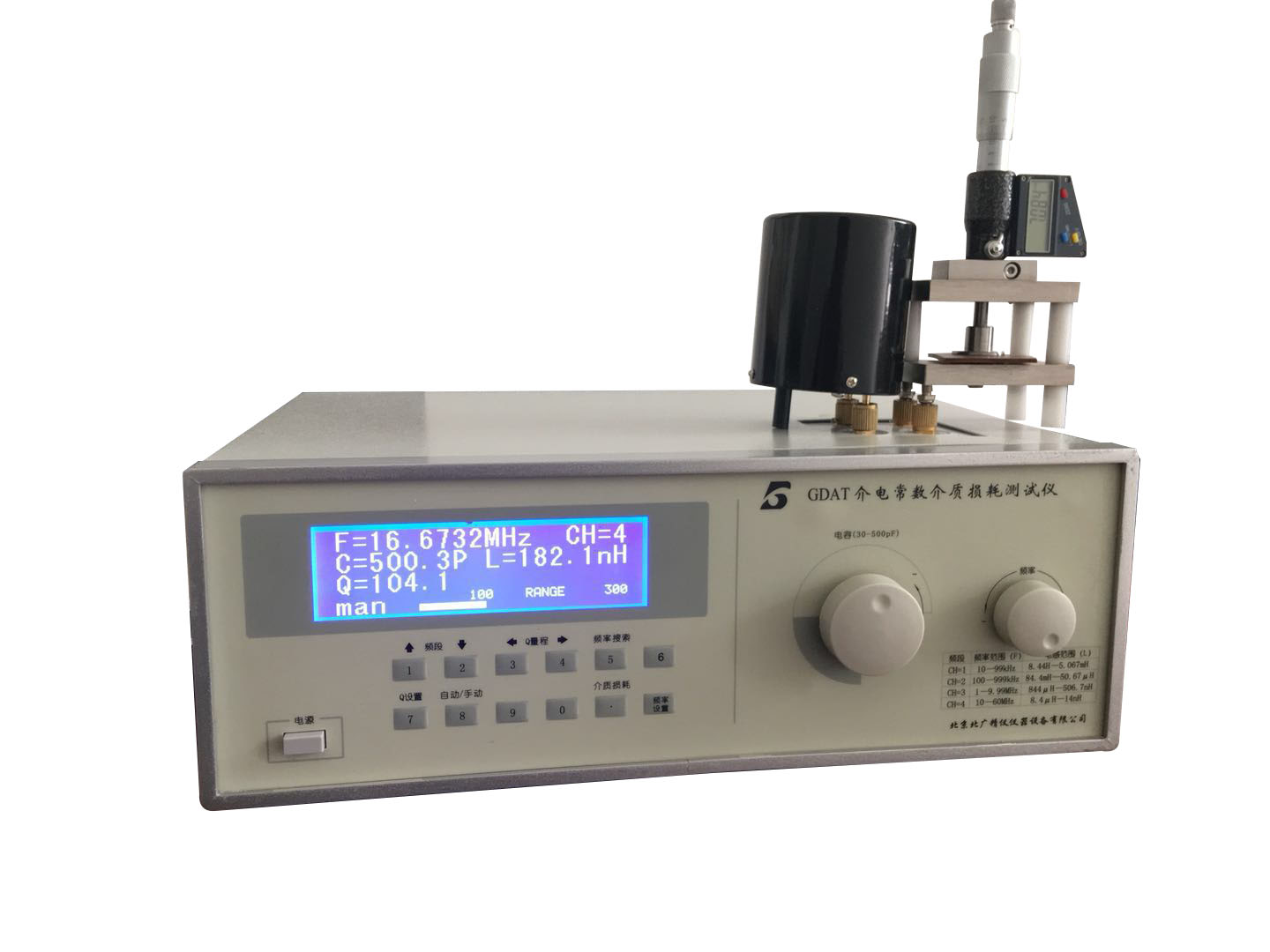
注:這個(gè)性質(zhì)不是絕對(duì)成立的。
對(duì)于絕緣性不太好的材料(就是說(shuō)不擊穿的情況下,也可以有一定的導(dǎo)電性)和絕緣性很好的材料比較,這個(gè)結(jié)論是成立的。
但對(duì)于兩個(gè)絕緣體就不一定了。
介電常數(shù)反映的是材料中電子的局域(local)特性,導(dǎo)電性是電子的全局(global)特征.不是一回事情的。
補(bǔ)充:
電介質(zhì)經(jīng)常是絕緣體。其例子包括瓷器(陶器),云母,玻璃,塑料,和各種金屬氧化物。有些液體和氣體可以作為好的電介質(zhì)材料。干空氣是良好的電介質(zhì),并被用在可變電容器以及某些類型的傳輸線。蒸餾水如果保持沒有雜質(zhì)的話是好的電介質(zhì),其相對(duì)介電常數(shù)約為80。
對(duì)于時(shí)變電磁場(chǎng),物質(zhì)的介電常數(shù)和頻率相關(guān),通常稱為介電系數(shù)。介電常數(shù)又叫介質(zhì)常數(shù),介電系數(shù)或電容率,它是表示絕緣能力特性的一個(gè)系數(shù)。
電極系統(tǒng)
1加到試樣上的電極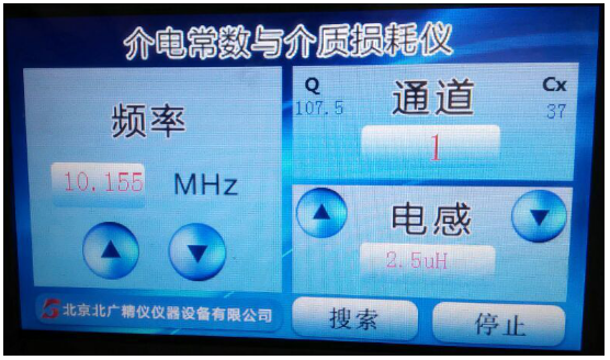
電極可選用5.1.3中任意一種。如果不用保護(hù)環(huán)。而且試樣上下的兩個(gè)電極難以對(duì)齊時(shí),其中一個(gè)電極應(yīng)比另一個(gè)電極大些。已經(jīng)加有電極的試樣應(yīng)放置在兩個(gè)金屬電極之間,這兩個(gè)金屬電極要比試樣上的電極稍小些。對(duì)于平板形和圓柱形這兩種不同電極結(jié)構(gòu)的電容計(jì)算公式以及邊緣電容近似計(jì)算的經(jīng)驗(yàn)公式由表1給出.
對(duì)于介質(zhì)損耗因數(shù)的測(cè)量,這種類型的電極在高頻下不能滿足要求,除非試樣的表面和金屬板都非常平整。圖1所示的電極系統(tǒng)也要求試樣厚度均勻
2試樣上不加電極
表面電導(dǎo)率很低的試樣可以不加電極而將試樣插人電極系統(tǒng)中測(cè)量,在這個(gè)電極系統(tǒng)中,試樣的一側(cè)或兩側(cè)有一個(gè)充滿空氣或液體的間隙。
平板電極或圓柱形電極結(jié)構(gòu)的電容計(jì)算公式由表3給出。
下面兩種型式的電極裝置特別合適
2.1空氣填充測(cè)微計(jì)電極
當(dāng)試樣插人和不插人時(shí),電容都能調(diào)節(jié)到同一個(gè)值,不需進(jìn)行測(cè)量系統(tǒng)的電氣校正就能測(cè)定電容率。電極系統(tǒng)中可包括保護(hù)電極.
2.2流體排出法
在電容率近似等于試樣的電容率,而介質(zhì)損耗因數(shù)可以忽略的一種液體內(nèi)進(jìn)行測(cè)量,這種測(cè)量與試樣厚度測(cè)量的精度關(guān)系不大。當(dāng)相繼采用兩種流體時(shí),試樣厚度和電極系統(tǒng)的尺寸可以從計(jì)算公式中消去
試樣為與試驗(yàn)池電極直徑相同的圓片,或?qū)y(cè)微計(jì)電極來(lái)說(shuō),試樣可以比電極小到足以使邊緣效應(yīng)忽略不計(jì)在測(cè)微計(jì)電極中,為了忽略邊緣效應(yīng),試樣直徑約比測(cè)微計(jì)電極直徑小兩倍的試樣厚度。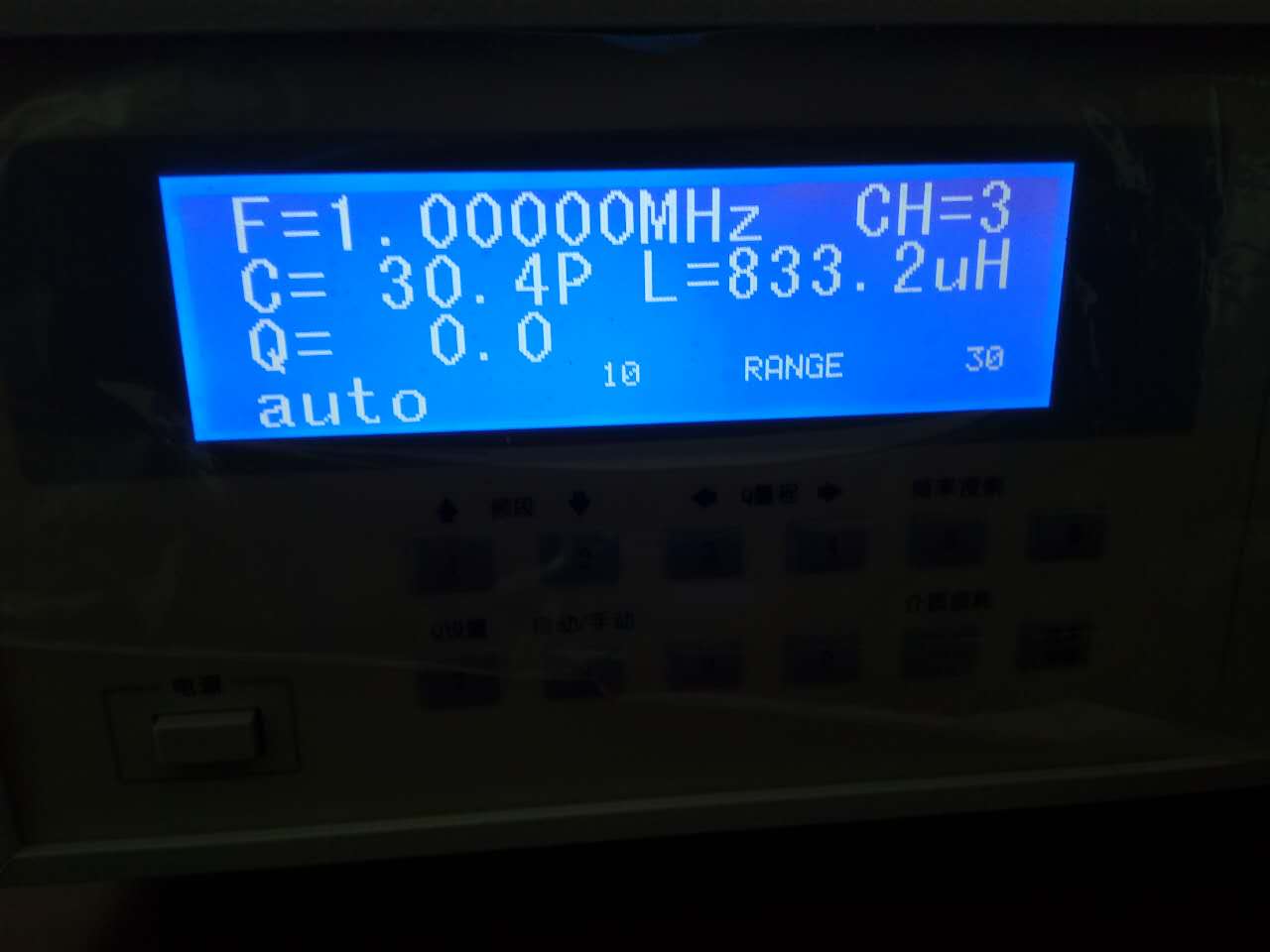
試驗(yàn)步驟
1試樣的制備
試樣應(yīng)從固體材料上截取,為了滿足要求,應(yīng)按相關(guān)的標(biāo)準(zhǔn)方法的要求來(lái)制備。
應(yīng)精確地測(cè)量厚度,使偏差在士(0. 2%士。.005 mm)以內(nèi),測(cè)量點(diǎn)應(yīng)均勻地分布在試樣表面。必要時(shí),應(yīng)測(cè)其有效面積。
2條件處理
條件處理應(yīng)按相關(guān)規(guī)范規(guī)定進(jìn)行。
3測(cè)量
電氣測(cè)量按本標(biāo)準(zhǔn)或所使用的儀器(電橋)制造商推薦的標(biāo)準(zhǔn)及相應(yīng)的方法進(jìn)行。
在1 MHz或更高頻率下,必須減小接線的電感對(duì)測(cè)量結(jié)果的影響。此時(shí),可采用同軸接線系統(tǒng)(見圖1所示),當(dāng)用變電抗法測(cè)量時(shí),應(yīng)提供一個(gè)固定微調(diào)電容器。
測(cè)量方法的選擇:
測(cè)量電容率和介質(zhì)損耗因數(shù)的方法可分成兩種:零點(diǎn)指示法和諧振法。
1零點(diǎn)指示法適用于頻率不超過(guò)50 MHz時(shí)的測(cè)量。測(cè)量電容率和介質(zhì)損耗因數(shù)可用替代法;也就是在接人試樣和不接試樣兩種狀態(tài)下,調(diào)節(jié)回路的一個(gè)臂使電橋平衡。通常回路采用西林電橋、變壓器電橋(也就是互感藕合比例臂電橋)和并聯(lián)T型網(wǎng)絡(luò)。變壓器電橋的優(yōu)點(diǎn):采用保護(hù)電極不需任何外加附件或過(guò)多操作,就可采用保護(hù)電極;它沒有其他網(wǎng)絡(luò)的缺點(diǎn)。
2諧振法適用于10 kHz一幾百M(fèi)Hz的頻率范圍內(nèi)的測(cè)量。該方法為替代法測(cè)量,常用的是變電抗法。但該方法不適合采用保護(hù)電極。
注:典型的電橋和電路示例見附錄。附錄中所舉的例子自然是不全面的,敘述電橋和側(cè)量方法報(bào)導(dǎo)見有關(guān)文獻(xiàn)和該種儀器的原理說(shuō)明書。
試驗(yàn)報(bào)告
試驗(yàn)報(bào)告中應(yīng)給出下列相關(guān)內(nèi)容:
絕緣材料的型號(hào)名稱及種類、供貨形式、取樣方法、試樣的形狀及尺寸和取樣日期(并注明試樣厚度和試樣在與電極接觸的表面進(jìn)行處理的情況);
試樣條件處理的方法和處理時(shí)間;
電極裝置類型,若有加在試樣上的電極應(yīng)注明其類型;
測(cè)量?jī)x器;
試驗(yàn)時(shí)的溫度和相對(duì)濕度以及試樣的溫度;
施加的電壓;
施加的頻率;
相對(duì)電容率ε(平均值);
介質(zhì)損耗因數(shù)tans(平均值);
試驗(yàn)日期;
相對(duì)電容率和介質(zhì)損耗因數(shù)值以及由它們計(jì)算得到的值如損耗指數(shù)和損耗角,必要時(shí),應(yīng)給出與溫度和頻率的關(guān)系。
特點(diǎn):
◆ 優(yōu)化的測(cè)試電路設(shè)計(jì)使殘值更小
◆ 高頻信號(hào)采用數(shù)碼調(diào)諧器和頻率鎖定技術(shù)
◆LED數(shù)字讀出品質(zhì)因數(shù),手動(dòng)/自動(dòng)量程切換
◆ 自動(dòng)掃描被測(cè)件諧振點(diǎn),標(biāo)頻單鍵設(shè)置和鎖定,大大提高測(cè)試速度
電感:
線圈號(hào) 測(cè)試頻率 Q值 分布電容p 電感值
9 100KHz 98 9.4 25mH
8 400KHz 138 11.4 4.87mH
7 400KHz 202 16 0.99mH
6 1MHz 196 13 252μH
5 2MHz 198 8.7 49.8μH
4 4.5MHz 231 7 10μH
3 12MHz 193 6.9 2.49μH
2 12MHz 229 6.4 0.508μH
1 25MHz,50MHz 233,211 0.9 0.125μH
Dielectric loss refers to the energy loss caused by the hysteresis effect of dielectric conductivity and polarization in insulating materials under the action of an electric field. Also known as dielectric loss, abbreviated as dielectric loss.
The dielectric loss factor refers to a parameter that measures the degree of dielectric loss.
Usage and maintenance
High frequency Q-meter is a relatively precise impedance measuring instrument, which can only ensure long-term stability and high testing accuracy under reasonable use and maintenance.
a. Familiarize yourself with this manual and use the instrument correctly;
b. Keep the instrument clean and dry regularly;
c. The warranty period of this instrument is 18 months. If mechanical failure or loss of accuracy is found, it can be returned to our factory in its original packaging for free repair.
Main configuration:
a. Test one host;
b. 9 inductors;
c. A set of fixtures
Testing precautions
a. This instrument should be placed horizontally;
b. If you need more accurate measurement, please preheat for 30 minutes after turning on the power;
c. When adjusting the main capacitor or digital switch of the main capacitor, please adjust slowly when approaching the resonance point;
d. The wiring between the tested component and the test circuit terminal should be as short and thick as possible, and should have good and reliable contact to reduce measurement errors caused by the resistance and distribution parameters of the wiring;
e. Do not place the test piece directly on the top of the panel, more than one centimeter away from the top. If necessary, use low loss insulation materials such as polystyrene to make padding;
f. Hands should not be close to the test piece to avoid measurement errors caused by human induction. For shielded test pieces, the shielding cover should be connected to the terminal at the low potential end.
Main technical features:
Dielectric loss and dielectric constant are important physical properties of various ceramics such as electrical ceramics, device ceramics, capacitors, and composite materials. By measuring the dielectric loss tangent tan δ and dielectric constant (ε), various factors affecting dielectric loss and dielectric constant can be further understood, providing a basis for improving material performance; The basic principle of the instrument is to use high-frequency resonance method and provide universal, multi-purpose, and multi range impedance testing. It uses a single-chip computer as the control of the instrument, and the measurement core adopts frequency digital locking, automatic setting of standard frequency test points, automatic search for resonance points, automatic conversion of Q value range, numerical display and other new technologies. It improves the tuning circuit, reduces the residual inductance of the tuning test circuit to the lowest, and retains the automatic amplitude stabilization technology in the original Q meter, making the new instrument more convenient to use and the measurement values more accurate. The instrument can measure the Q value of high-frequency inductors or resonant circuits, the inductance and distributed capacitance of inductors, the capacitance and loss tangent of capacitors, the high-frequency dielectric loss of electrical materials, the effective parallel and series resistance of high-frequency circuits, and the characteristic impedance of transmission lines under high testing frequency conditions.
Why does the larger the dielectric constant, the stronger the insulation ability?
Because the dielectric constant of a substance is frequency dependent, it is commonly referred to as the dielectric constant.
Dielectric constant, also known as dielectric constant, dielectric constant or permittivity, is a coefficient that represents the insulation capability characteristics. So theoretically, the larger the dielectric constant, the better the insulation performance.
Note: This property is not absolutely valid.
This conclusion holds true when comparing materials with poor insulation (meaning they can still have some conductivity without breakdown) to materials with good insulation.
But not necessarily for two insulators.
The dielectric constant reflects the local characteristics of electrons in a material, while conductivity is the global characteristic of electrons It's not just a one-time occurrence.
Addendum:
Dielectric materials are often insulators. Examples include porcelain (pottery), mica, glass, plastic, and various metal oxides. Some liquids and gases can serve as good dielectric materials. Dry air is a good dielectric and is used in variable capacitors and certain types of transmission lines. Distilled water is a good dielectric if it remains free of impurities, with a relative dielectric constant of about 80.
For time-varying electromagnetic fields, the dielectric constant of matter is frequency dependent and is commonly referred to as the dielectric constant. Dielectric constant, also known as dielectric constant, dielectric constant or permittivity, is a coefficient that represents the insulation capability characteristics.
Electrode system
1. Electrode added to the sample
The electrode can be selected from any of 5.1.3. If no protective ring is needed. And when the two electrodes on top and bottom of the sample are difficult to align, one electrode should be larger than the other. The sample with electrodes already added should be placed between two metal electrodes, which are slightly smaller than the electrodes on the sample. The capacitance calculation formulas for flat and cylindrical electrode structures, as well as the empirical formulas for approximate calculation of edge capacitance, are given in Table 1
For the measurement of dielectric loss factor, this type of electrode cannot meet the requirements at high frequencies unless the surface of the sample and the metal plate are very flat. The electrode system shown in Figure 1 also requires uniform sample thickness
Two samples without electrodes added
Samples with low surface conductivity can be measured by inserting them into an electrode system without adding electrodes. In this electrode system, there is a gap filled with air or liquid on one or both sides of the sample.
The capacitance calculation formula for flat or cylindrical electrode structures is given in Table 3.
The following two types of electrode devices are particularly suitable
2.1 Air filled micrometer electrode
When the sample is inserted or not, the capacitance can be adjusted to the same value without the need for electrical calibration of the measurement system to determine the capacitance rate. The electrode system may include protective electrodes
2.2 Fluid Discharge Method
Measuring in a liquid with a capacitance rate approximately equal to that of the sample and a negligible dielectric loss factor is not closely related to the accuracy of sample thickness measurement. When two fluids are used successively, the thickness of the sample and the size of the electrode system can be eliminated from the calculation formula
The sample is a circular disc with the same diameter as the electrode of the test cell, or for the micrometer electrode, the sample can be small enough to ignore edge effects in the micrometer electrode. In order to ignore edge effects, the sample diameter is approximately twice the thickness of the sample, which is smaller than the diameter of the micrometer electrode.
Experimental steps
Preparation of Sample 1
The sample should be taken from the solid material and prepared according to the relevant standard methods to meet the requirements.
The thickness should be measured accurately so that the deviation is within ? 0 2% of the population Within 0.05 mm, the measuring points should be evenly distributed on the surface of the specimen. If necessary, its effective area should be measured.
2 Condition Handling
Condition handling should be carried out in accordance with relevant regulations.
3 Measurements
Electrical measurements shall be conducted in accordance with this standard or the standards and corresponding methods recommended by the manufacturer of the instrument (bridge) used.
At frequencies of 1 MHz or higher, it is necessary to reduce the influence of the inductance of the wiring on the measurement results. At this point, a coaxial wiring system (as shown in Figure 1) can be used, and when measuring using the variable reactance method, a fixed fine-tuning capacitor should be provided.
Selection of measurement methods:
There are two methods for measuring capacitance and dielectric loss factor: zero point indication method and resonance method.
The zero point indication method is applicable for measurements with frequencies not exceeding 50 MHz. Alternative methods can be used to measure capacitance and dielectric loss factor; That is, adjust one arm of the circuit to balance the bridge in both the state of connecting and not connecting the sample. Usually, circuits use Xilin bridge, transformer bridge (i.e. mutual inductance coupled proportional arm bridge), and parallel T-shaped network. The advantages of transformer bridge: the use of protective electrodes does not require any additional accessories or excessive operation, and protective electrodes can be used; It does not have the drawbacks of other networks.
The resonance method is suitable for measurements in the frequency range of 10 kHz to several hundred MHz. This method is an alternative measurement method, commonly used is the variable reactance method. But this method is not suitable for using protective electrodes.
Note: Typical examples of bridges and circuits can be found in the appendix. The examples given in the appendix are naturally not comprehensive. The description of the bridge and measurement methods can be found in relevant literature and the principle manual of the instrument.
Test report
The following relevant content should be provided in the test report:
The model name and type of insulation material, supply form, sampling method, shape and size of the sample, and sampling date (with the thickness of the sample and the treatment of the sample on the surface in contact with the electrode indicated);
The method and processing time for sample condition treatment;
The type of electrode device, if there are electrodes added to the sample, their type should be indicated;
Measuring instrument;
The temperature and relative humidity during the experiment, as well as the temperature of the sample;
Applied voltage;
Applied frequency;
Relative permittivity ε (average value);
Dielectric loss factor tan (average value);
Test date;
The values of relative permittivity and dielectric loss factor, as well as the values calculated from them such as loss index and loss angle, should be given in relation to temperature and frequency if necessary.
characteristic:
Optimized test circuit design reduces residual value
High frequency signals use digital tuner and frequency locking technology
◆ LED digital readout quality factor, manual/automatic range switching
◆ Automatically scan the resonance point of the tested component, set and lock the standard frequency with a single key, greatly improving the testing speed
Inductance:
Coil number test frequency Q value distribution capacitance p inductance value
9 100KHz 98 9.4 25mH
8 400KHz 138 11.4 4.87mH
7 400KHz 202 16 0.99mH
6 1MHz 196 13 252μH
5 2MHz 198 8.7 49.8μH
4 4.5MHz 231 7 10μH
3 12MHz 193 6.9 2.49μH
2 12MHz 229 6.4 0.508μH
1 25MHz,50MHz 233,211 0.9 0.125μH